


In this article let us learn about what assembly language is and how we can write assembly language codes.
Why assembly?
So, why do we need to learn this language? We all have used and seen the application of high-level programming languages like Python, Javascript, C++, Java, and so many others. Have you ever wondered what happens as and when we run these programs/codes? Have you ever thought about how our programs work the way we want them to? Well, to get a clear picture of what happens, we need to have some understanding of the assembly language.
All the complex and amazing programs we write won't be directly understood by our computer as it requires all the instructions to be fed in form of zeros and ones (machine level language). For this to happen, we have separate programs called compilers in our systems that covert our codes into machine-understandable ways. As we understand what the compiler translates the source code into that runs on the CPU, we will be able to write a more efficient program in terms of memory space.
Assembly language was created as a shortcut for machine level coding, so that we wouldn't have to count 0s and 1s all day. By learning assembly language, we will be able to directly communicate with the hardware of the system like processors.
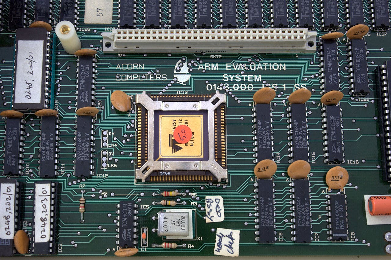
In this article, we will mainly look into the programming of one of the powerful processors called ARM. There are lots of laptops and systems that work on these processors. ARM stands for Acorn RISC Machines and is a leading provider of 32 bit embedded microprocessors. The ARM processor is a RISC (Reduced Instruction Set Computer) processor which means the number of lines of code in the program increases but the amount of work done by individual instruction is reduced. Also, we will learn encoding of assembly language to machine level language of zeroes and ones.
Enough of theory. Let's dive into the real fun coding.
.text
ARM Instruction 1
ARM Instruction 2
ARM Instruction 3
                .
                .
                .
ARM Instruction n


.data
Variable declaration 1
Variable declaration 2
                     .
                     .
                     .
Variable declaration n
This is a basic syntax of how we go about writing ARM programs. All the variable declarations go under .data section and all the other main codes go under .text section.
Every instruction of the program will be assigned an address during execution as below. The use case of this will be understood when we look into branch instructions in the future.
.text
Address of Instruction 1          ARM Instruction 1
Address of Instruction 2          ARM Instruction 2
Address of Instruction 3          ARM Instruction 3
                          .
                          .
                          .
Address of Instruction n          ARM Instruction n


.data
Address of Data 1                 Variable declaration 1
Address of Data 2                 Variable declaration 2
                   .
                   .
                   .
Address of Data n                Variable declaration n
To run the ARM codes, we can install and use an ARM simulator that looks like this.
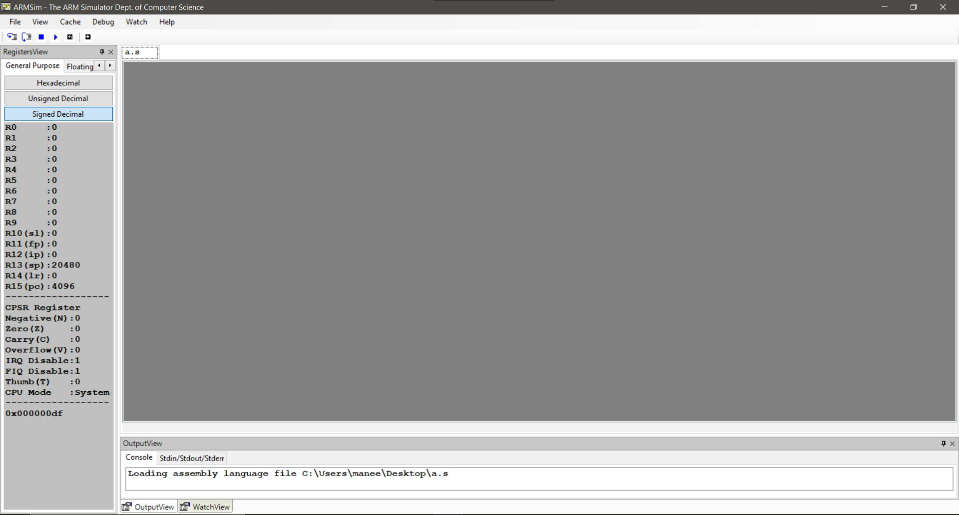
In this article, we will briefly look into the codes that we can run on this simulator. We will also look into how codes of a high-level language can be written using assembly language.
Registers
Before diving deep into coding, we need to understand how registers work in ARM. We have a total of 37 registers provided all of which can hold 32 bits. Out of these 37 registers, 30 are general-purpose registers, 5 are SPSR, 1 CPSR, and 1 PC. Let's see what these are.
The current status of the program under execution, such as result of current execution instruction is zero / -ve are captured in CPSR (Current Program Status Register).
The ARM has seven basic operating modes like User, System, IRQ, Supervisor, Abort, Undef, and FIQ. Certain instructions run on certain modes only based on the priorities and interrupts.
Sometimes, when interrupts occur, modes have to be changed to handle higher priority programs. While shifting from one mode to another mode, CPSR contents will be copied to SPSR (Saved program Status Registers). SPSR contents will be copied back to CPSR when it returns back to the previous mode.
PC - Program Counter is a register that stores the memory address of the next instruction to be executed.
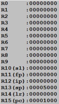
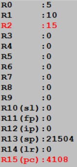
This is how the register bank looks like in the ARM simulator. In the user mode, R0 to R12 are general purpose registers, R13 is a stack pointer register, R14 is the link register and R15 is the Program counter. We will look into the uses of these as we go further.
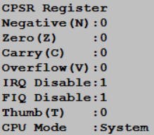 This is how the CPSR looks like. It has a bunch of information regarding the current program that is running. We will discuss these soon in the coming examples.
Variables
Let's understand what .data contains. As told earlier, this section holds all the variables of the program. ARM is a 32-bit architecture which means it can hold values that are up to 32 bits long. When used in relation to ARM, Byte means 8 bits, Halfword means 16 bits and Word means 32 bits.
ARM processors support six data types:
- 8-bit signed and unsigned
bytes. - 16-bit signed and unsigned
half-words(These are aligned on 2-byte boundaries). - 32-bit signed and unsigned
words(These are aligned on 4-byte boundaries).
Below is a basic code to declare variables
.data
a: .word 100
b: .word 200
According to the above declarations, we have two variables a and b of data type word. Also, a contains a value of 100 and b contains a value of 200. To process any of these values, we will have to transfer the data into the registers.
Instructions
General syntax or format of instructions is
Mnemonic{condition}{S} {Rd}, Operand1, Operand2
Here, Mnemonic is a short form of the basic operation we would want to perform such as ADD (for addition), SUB (for subtraction), etc.
{condition} can be anything that is needed to be met in order for the instruction to be executed like EQ(equal), MI(minus), GT(greater than), LT(less than), etc.
{S} is an optional suffix used to update CPSR flags on the result of the operation. We have already discussed what CPSR is under the Register section. More about this has been discussed in the second example program below.
{Rd} is a destination register for storing the result of the operation.
Operand1 and Operand2 are the first and second registers or immediate values.
Let us look at some codes in general. Later we will discuss each instruction topic-wise.
Install the simulator and try coding these examples.
//Example 1)
.text
MOV R0, #5
MOV R1, #10
ADD R2, R0, R1
According to the above code, we are moving a value of 5 to register R0 and a value of 10 to register R1. Finally, we are adding these register contents and storing them in the register R2. Below is the register output screenshot from the simulator
//Example 2)
.text
MOV r0, #-10
MOV r1, #-10
ADDS r2, r1,r0
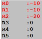
As mentioned in the syntax, whenever S is used after ADD, it means to tell the CPSR to update its values.
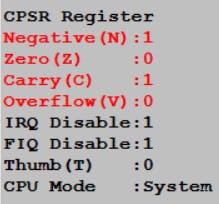
N - Negative: Set to 1 if the result of previous instruction is negative.
Z - Zero: Set to 1 if the result of previous instruction is Zero.
C - Carry: Set to 1 if the result produces a carry-out in an arithmetic operation.
V - Overflow: Set to 1 if the previous instruction produces an overflow into the sign bit.
Thumb (T) - 16-bit instruction set for improved performance from memory with a narrow data bus
IRQ and FIQ disable bits mainly deals with the high priority instructions
//Example 3)
.text
MOV r0,#-20
MOV r1,#5
SUBS r2,r0,r1
ADDMIS r0,r0,r1
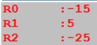
The above code subtracts r1 from r0 (r0 - r1) and saves it into the CPSR register (because of S in SUBS). {condition}, i.e MI (means minus condition) has been used here which means r0 and r1 are added only if N is set to 1 in the CPSR register. Since S is used after ADDMI, once again CPSR registers are updated based on this instruction.

This is a small overview of how ARM instructions are coded. High-level languages make it so simple to write codes that are understood by our systems. Assembly is just one step away from machine code, so it is often useful to read and determine what the compiler has done.
Don't feel frustrated if you are confused at this point. With practice and more examples, these will become much more clear and you will feel more confident in coding ARM instructions. From now on, let's discuss the instruction codes topic-wise.
Data processing instructions
Data movement :
These can be interpreted as variable declaration of high level languages
MOV and MVN
These instructions are used to move values to a register. The first code below moves a value of 10 to R2, whereas the next code moves the value R2 to R5 and sets CPSR register values.
MOV R2, #10
MOVS R5, R2
MVN stores NOT of the operand to the register
MVN r0, #4
The above code would result in -5 being stored in r0.
Arithmatic operations :
Here goes the syntax <Operation>{<cond>}{S} Rd, Operand1, Operand2
<cond> and S are optional and can be used only if necessary. Rd is destination register, Operand1 and Operand2 can be general purpose registers or also immediate values (integer numbers like 5).
ADD R0, R1, R2
SUB R0, #10, #5
RSB R0, R1, #5
RSB stands for reverse subtraction. The above code can be understood as R0 = R1+R3, R0 = 10-5, R0=5-R1.
MUL stands for multiplication. The below code would multiply R0 and R1 and store the result in R2 register.
MOV R0, #25
MOV R1, #5
MUL R2, R0, R1
MLA R5, R1, R2, R4
This is multiplication and accumulate operation, which means it would multiply R1 and R2, add the product with R4 and store back the result to R5.
R5 = (R1 X R2) + R4
This is how arithmetic operations work.
Comparision operations :
These instructions are mainly used to compare the register values and then perform certain other instructions based on this. Just like the if and else statements we use in high level languages.
<Operation>{<cond>} Rn, Operand2 is the basic syntax. Again, {<cond>} is optional and can be committed if not required. Also, we don't have to mention S in these instructions as comparison operations automatically update CPSR flag values.
CMP, CMN, TST, TEQ are the main operations that come under this.
Firstly, let us assign values to two registers and perform the operations on them.
MOV R1, #10
MOV R2, #10
CMP R1, R2
CMP does R1 - R2 and updates the CPSR register values to check if the values are equal or not. In case, R1 - R2 results in zero, Z will be updated to 1 in CPSR and it means registers contain equal values.
The CMN instruction adds the value of R2 to the value in R1. This is the same as an ADDS instruction, except that the result is discarded.
CMN R1, R2
TST does R1 AND R2. In general, The AND operator is a boolean operator used to perform a logical conjunction on two operands.
TST R1, R2
TEQ does R1 OR R2. In general, The OR operator is a boolean operator used to perform a logical disjunction on two operands.
TEQ R1, R2
Here's a simple use-case of the above
MOV R0, R1
TST R0, #1
The above code checks if R1 contains an even or odd number. Running this would lead to the Z flag of CPSR to be zero or one based on the value of R1. As told earlier, TST performs AND operation. Therefore AND operation is performed on R1 and 1. If the last digit of the binary form of R1 has zero, AND operation with 1 leads to zero of all digits (bits). This means the Z flag of CPSR gets updated to 1, indicating an even number.
Let's look into an example. Suppose R1 contains a value 6. Six in binary would be 0110 and one in binary would be 0001. Result of AND operation between these is zero indicating even number.
0110
0001
-----
0000
-----
Suppose R1 contains a value 5. Result is 1 indicating odd number
0101
0001
-----
0001
-----
This is how we can check for even and odd numbers using ARM instructions
Branching operations
B and BL are the two main branching operations we have. Branching is nothing but flow control instructions. These are similar to goto instructions of C language. In these operations, we will learn how program counter (PC) and Link register (R14) are useful.
        MOV R0, #0
loop:
        ADD R0, R0, #1
        CMP R0, #10
        BNE loop
The above code shows us how the for loops in most of the languages are done in ARM instructions. Firstly, we have 0 in R0. Every time, 1 is added to R0 and stored back to R0. R0 is compared with 10. BNE is Branch Not Equal, which means branch to loop if R0 is not equal to 10. Once R0 contains 10, BNE won't get executed and we come out of the loop.
Syntax B{<cond>} label. In the above example, NE was the {<cond>}. As told earlier, the program counter contains the address of the next operation to be executed. So whenever we call B instruction, PC contains the address of the label. In the above example, loop was the label.
BL is very similar to B instruction except that we have one more operation that takes place along with branch instruction. In BL, firstly PC will be copied to R14 (Link Register) before the branch is taken. Then, the program counter is assigned the label . These are required when we have to go back to the previously executed instruction after the branch instructions are over.
        MOV R2, #0
        BL plus
        CMP R2, #5
        MOVEQ R3, #1
plus:
        ADD R2, R2, #5
        MOV PC, R14
In the above example, we see a clear example of the need for BL instruction. R2 initially contains 0. When the plus branch is taken, R14 (link register) will hold the value of current PC, that is the address of instruction at line number 3. In the branch instruction, R2 gets incremented by 5 and then R14 value is copied back to PC. This means now the PC has the address of the instruction of line number 3 and hence CMP, R2 is compared to 5. If true, R3 gets a value of 1.
This is how loops, if and else conditions are written in assembly-level language.
Data transfer instruction
These instructions mainly deal with moving data between registers and memory. The basic operations include LDR and STR for data transfer.
LDR - Load word into register
STR - Save word into memory from register
LDRB - Load byte into register
STRB - Save byte into memory from Register
The syntax is as follows <LDR/STR>{<cond>}{B} Rd, Addressing. Refresh the data types knowledge which we have already discussed in the Variables section above.
Consider a scenario where we would have to copy the value from one variable to another variable. This is how it would be done.
A has a value of 100. Copy A to B.
.text
LDR R1, =A
LDR R2, =B
LDR R4, [R1]
STR R4, [R2]

.data
A: .word 100
B: .word 0
The above example copies the value stored in A to B. In the variable section (.data), we have two variables A and B both of word datatype. A contains 100 and B contains 0.
Initially, A address is copied to register R1 and B address is copied to R2. Next LDR, the data in the address of R1 is copied to R4=100. This is why it is called as load. In the STR instruction, 100 is stored in the address specified by R2 i.e B. Hence the value of A is copied to B in this manner.
Software Interrupts
Interrupts are anything that brings a temporary halt to the current working process. These interrupts can happen due to various reasons like - application may make a system call, instructions may be executed illegally (dividing by zero), etc.

In ARM, we use SWI to denote Software interrupts while coding. These are the interrupts that are triggered by software instructions.
SWI is a user-defined instruction. By making use of this, an operating system can
implement a set of privileged operations which applications running in user mode can request.
SWI 0x11
The above code is used for terminating the current program. If an infinite loop is encountered, this piece of code can be run and the process can be ended logically.
SWI 0x00
SWI 0x02
The above two codes are used for display purposes. 0x00 is used to display a single character and 0x02 is used to display a string.
SWI 0x66
SWI 0x68
SWI 0x69
SWI 0x6a
0x66 - Open a file
0x68 - Close a file
0x69 - Write string to a file
0x6a - Read string from a file
.text
LDR R0, =B
SWI 0x02
SWI 0x11

.data
B: .asciz “HELLO WORLD”
The above program is a procedure to display a string on the screen using ARM.
Encoding
Until now, we have discussed how we can write high-level language codes in assembly language. Now let us look into our system's language that is zeroes and ones.
Encoding is a process of converting the assembly level language to machine level codes of zeroes and ones which our system can understand. This process is usually done by the compiler. Different types of instructions have different encoding methods. In this section, we will discuss data processing instructions encoding.

Recalling the syntax once again - OPcode{condition}{S} Rd,Operand1,Operand2
As told earlier, the instructions are 32 bit in length.
Bits 28 to 31 decide the condition of the instruction like EQ(equal), NE(Not equal), LT(Less than), GT(Greater than etc). These are 4 bits in length. For example,
0000 implies EQ
0001 implies NE and so on.
Bits 26 and 27 are usually 0.
Bit number 25 defines whether the instruction has an immediate value or not. We will look at this more in the example soon.
Bits 21 to 24 decide the opcode. Opcode is nothing but the operation performed like ADD, SUB, CMP, etc
0000 - ADD
0010 - SUB
1010 - CMP
Bit number 20 is the S value which defines whether the CPSR flags must be updated or not.
Bits 16 to 19 represent operand1 register,
12 to 15 represent destination register,
Rest are for operand2 register and some other properties like shift values.
Let's look at a simple example
ADD R1, R0, R2
This is a simple data processing instruction of adding two registers R0 and R2 and storing the result into R1.
This is how it would look like when converted to binary -
1110 0000 1000 0000 0001 0000 0000 0010
Let's break this step by step.

This picture has to be kept in mind while converting data processing instructions to binary. Since there is no condition here, the condition 4 bits become 1110 which indicates always. This means that the above instruction runs always no matter what the condition is.
The next two bits are however zero as we discussed earlier.
Bit 25 is zero because there is no immediate value in the instruction. For example, in ADD R1, R0, #5, #5 would be the immediate value. But in our example, we have taken both the operands as registers and hence no immediate value.
0100 indicates it is an ADD operation
Since S is not added after ADD operation, bit number 20 is zero
0000 indicates R0
0001 indicates R1
Bits 4 to 11 deal with shift operations which are slightly out of scope for this article and we haven't discussed it here.
The last four bits 0010 indicates R2 register
This is a common procedure of converting assembly-level language to machine-understandable language. As we see, writing binary language is really difficult and time-consuming for programmers. That is the main reason we write codes in assembly language and other higher-level languages
By this, we come to the end of the article. This was just a small effort to discuss the assembly language and its use cases. We need to thank the programmers for developing high-level languages which make coding so much fun and enjoyable.
Keep learning !
-Maneesh